Monday, November 11, 2013

The Case For and Against TES for Campus Chilled Water Systems

As defined by ASHRAE, thermal energy storage (TES) systems are systems that remove heat from a storage medium (like water or ice) for use at another time.  The primary objective of a TES system is to reduce the on-peak electrical demand charges and therefore the cost of system operation.  A TES system can significantly reduce the cost of energy by allowing power intensive, electric driven cooling equipment to be predominantly operated during utility off-peak hours when utility electrical demand charges are reduced.  A TES system can theoretically shift all or part of the demand charges for the generation of cooling energy to utility non-peak hours, dependent only on the arrangement and physical size (capacity) of the storage vessel.  Thus these systems are principally designed to reduce energy cost.

Over the years, TES systems have been credited with saving energy as well.  Energy is equal to power (kW) multiplied by time (hours) or for electricity, kilowatt-hours (kWh).  For cooling energy, the equation is still power (tons) multiplied by time (hours) to yield ton-hours of cooling energy.  The TES system has the capability of shifting the generation of these ton-hours from peak to non-peak utility times thus saving cost, but not energy.  Any slight energy savings that may be available from operating a chiller at full load for more hours or operating at night with lower condensing temperatures will generally be offset by tank temperature losses and inefficiency in operation of the control system storing and releasing chilled water to the loads.

In addition, TES systems have also been considered as a substitute for redundant chiller capacity.  Whether or not this is true depends on one’s definition of a redundant chiller. All TES systems are designed based on a time component, back to cooling energy in ton-hours.  Consider a three chiller plant with no redundant chiller capacity.  Adding a storage tank that is used principally for the peak shaving of electrical demands to provide redundant capacity only makes sense if excess chiller capacity was available the day before.  If the true design load was three chillers, by the evening of the first day, the capacity of the tank has certainly been depleted and if the design load continues with two chillers, no other mechanism is available to make the excess chilled water for the TES system.  Even if the tank is just kept cold and kept in reserve (not used for peak shaving) until one of the three chillers fail, it could only be considered a redundant chiller for one day.

The concept of storing chilled water in the volumes required for a campus TES system has a disadvantage that is concerning from a redundancy and safety standpoint.  The typical campus cooling system is a closed, pressurized chilled water system with very little leakage over time and therefore very little make-up water introduced into the system.  Since the storage tank sizes required for a TES system cannot be constructed as pressure vessels, the connection of the TES storage tank converts the closed chilled water system into an open system.  The obvious issue here is that controls and control valves must be relied upon to maintain the level of water in the tank even when the supply and return line connections both have the capability of quickly overflowing the tank and disabling the chilled water system.  A less obvious issue is that the tank must be vented, putting air above a very large surface of chilled water.  Such water readily absorbs oxygen, making the chilled water system and its piping significantly more prone to corrosion with the oxygenated water.  Neither of these are insurmountable issues but they are further considerations in the desirability of a TES system.

The chilled water system could remain closed if a heat exchanger were inserted at the union of the storage system and the closed chilled water system.  However even with extremely effective plate frame heat exchangers, there must be some temperature difference between the stored chilled water and the chilled water in the closed system, thus further complicating the operation of the storage system.

Lastly, since the system saves only energy cost, it is completely dependent on the local electrical rate for on-peak vs. off-peak power.  Some Owners may find that relying on a 10 year payback based on the current electrical rate schedule more risky that competing energy cost reduction techniques.


Author:  Jerry Williams

Wednesday, July 3, 2013

Engineers Without Borders - 8760 Style

I have always looked for a good challenge, to travel, and to be able to help other people.  With Engineers without Borders (EWB), I found a great outlet for all of these and more.  Engineers without Borders has been a life changing experience for me. My name is Ryan Hoff, and I am an intern at 8760 Engineering. My experience with Engineers without Borders of Missouri University of Science and Technology (EWB-S&T) has helped me in many aspects of my life, but I feel that for all the good that it does not enough people know about it. 
I have been involved with EWB-S&T for three years at Missouri S&T, formerly University of Missouri-Rolla.  Our chapter has four projects working in Bolivia (2), Guatemala, and Honduras.  We focus on providing sustainable engineering projects to improve the standard of living in developing countries.  Since I have been most involved in the Guatemala project, I will discuss this project the most. We work in Nahualate, Guatemala a village of 2200 people, who have requested for us to help them with their potable water project.  To accomplish this we will construct a 15,000 gallon water tower, 8 miles of PVC piping, a 430 ft. deep well, and a chlorine sanitation system.  All of the analysis and design are done by the student team and approved by professional engineers. The project began five years ago with a feasibility study.  The project continued with several assessment trips where the team surveyed the whole community, met with contractors, and worked with the community to gauge the community’s needs and wants.  The well was successfully completed (after the second try) in September 2012.  The team and I are returning this month to begin the construction of the distribution system.  We will focus on teaching the community on how to read and understand our designs, and we will teach proper construction techniques.  The community will be responsible for completing the pipe construction in our absence. We will also be teaching the Water Committee and community about the operation, maintenance, and management of their large system. EWB-USA focuses on not only providing a large capital project, but also being able to create a sustainable project.  EWB-S&T donates their time and the initial capital cost to the community, but the community will be responsible for paying for running costs such as electricity cost and replacement parts.  
This is just one project of one chapter of EWB-USA. Engineers without Borders-USA has over 250 student and professional chapters across the United States. Missouri has five student chapters and two professional chapters.   
After I return from my trip, I will go into greater detail of how EWB has helped me on both the professional and personal level.  I will discuss a few lessons I learned that have applied to work I have done at 8760 Engineering.  I may also tell a few good stories about my trip, and what I have learned from living in a developing country.  Until then, you can check out the links below, look at the pictures below, or send me an email if you have any questions.
For more information you can see some of the following links:


Article Author: Ryan Hoff


Monday, April 22, 2013

Fan Efficiency Grade: New Tool or Just Another Example of Relearning Something We Already Knew

I know last time I promised that my next contribution would be an explanation of why the supply air temperature wasn’t necessarily going to be 55°F.  I’ll get back to that later – I promise.  But right now, my thoughts seem to be heading in a new direction.  I just reviewed an excellent paper for HPAC Engineering Magazine on the concept of Fan Efficiency Grade (or FEG as it is being referred to).  Within a few days of that review, I heard an excellent talk at the St. Louis ASHRAE Chapter meeting by the President of AMCA, Mr. Vic Colwell, on the same topic.  For those of you looking to learn about one more constraint on your air handling systems design, ANSI/AMCA 205-12 Energy Efficiency Classification for Fans will provide some good bedtime reading (www.amca.org/feg/codes-and-standards.aspx). 

The idea of selecting fans of high efficiency is a concept that every engineer doing air systems design is fully aware of and embraces as a cornerstone of reducing energy use in these systems.  The idea of mandating an efficiency that is “acceptable” may slice against your grain but all would agree it’s a good and noble idea.  But it seems to me that fan efficiency really is a pretty small part of the overall picture.  Going back to the basics, the theoretical fan power (and therefore energy as it operates) to circulate air in an air duct system is given by the equation:
 
Fan Power = [(cfm)(FTP)]/[(6356)(ηT)]

Where  Fan Power =       Fan power needed not counting drive or motor losses (HP)
                cfm =                     Volumetric airflow rate (ft3/min)
                FTP =                     Fan total pressure (in wg)
                ηT =                        Fan total efficiency (decimal)               
                6356 =                   Constant to convert to horsepower

So obviously, the higher the fan efficiency, the lower the HP required.  So the FEG concept makes sense.  But there are still two more terms in the equation, the airflow required in cfm and the pressure required to overcome the air handling unit and duct system losses that establish the FTP.  The air quantity is set by the thermodynamics of the design and the load that is to be offset.  The designer has some leeway with this term but not a great deal.

That leaves the last factor, the fan total pressure.  And while the configuration of the building and the application may vary, this is a parameter that is almost totally established by the design of the system – and therefore, the designer.  Time to wake up - that’s us!  Though ASHRAE 90.1 has tried to weigh in on the topic of maximum fan pressure allowed, few designers understand it and even fewer code officials enforce it.  The next edition of ASHRAE 90.1 in 2013 will include prescriptive requirements for fan efficiency grade so get ready.  But the problem is really more fundamental than that.  This time we’ll look at just the system of ductwork and its design.  On another installment, we’ll look at how air handling unit design can also have an impact on that fan total pressure term.  But for now, let’s stick to ductwork.

With the types of projects we work on, we get to see lots of air system designs that are done by other engineering firms.  And although the drawings today are done in AutoCAD and are very professional looking, the thought that went into them has often not kept pace with the technology that produced them.  One of our partners has referred to duct designs that appear to be “puked up” on the page.  That may be a little too graphic (or too gross) for some but it does convey the meaning pretty clearly – the duct systems meander around the building so randomly that you wonder if there was any planning in the overall duct layout at all.

Sure, I can hear you saying it now … duct layouts, air distribution, layout organization and planning, it all sounds so 1970’s, it’s a waste of time - we’ve moved on to much more important stuff now.  We do have a lot more to think about now.  But I just want to remind you that some of that boring stuff makes your systems work better and save energy.  Please don’t forget that the basics are still important!

I’m going to proceed now to give you what I believe to be the five laws of air distribution and duct layout.  There will be some naysayers in the group who want to argue about these but I’m willing to take my chances.

Law No. 1KEEP IT SIMPLE

·         The shortest distance between two points is still a straight line; the shortest possible route requires less ductwork (less cost) and the lowest pressure drop (less fan power required)
·         There is nothing inherently wrong with a 45° elbow
·         An experienced sheet metal contractor I remember from when I was a pup told me “Engineers almost always get themselves in trouble when they run air past itself”

Law No. 2KEEP IT SYMMETRICAL

·         Attempt to use the duct geometry to provide an inherently balanced design
·         Terminal boxes (VAV boxes, mixing boxes, reheat boxes) should be located on the same side of the trunk duct as the area they serve
·         Terminal boxes should be centered with respect to the diffusers served to be more self-balancing

Law No. 3MAKE THE SYSTEM BALANCEABLE

·         Provide volume dampers to balance runouts with differing pressure needs (which always exist)
·         Avoid diffusers mounted to the side of ductwork to avoid noise and drafts
·         Design the ductwork so that the total supply airflow can be measured with a pitot tube traverse at one or two locations
·         Locate volume dampers as far from the supply diffusers as possible; avoid the use of registers for supply or return

Law No. 4LET THE AIR DISTRIBUTION DESIGN CONTROL THE DUCT DESIGN, NOT VICE VERSA

·         Don’t blow (or throw) from a ceiling diffuser in any direction further than the ceiling height
·         For selecting diffusers for VAV systems, look at diffuser performance at minimum flow as well as maximum flow
·         It may seem trivial but there is a lot to know about air distribution; take some time to study Chapter 20 in the 2009 ASHRAE Handbook of Fundamentals
·         For each new air distribution situation you encounter, test at least one space with the Air Diffusion Performance Index (ADPI – calculation described in Chapter 20)

Law No. 5BE CAUTIOUS WHEN MIXING AIR STREAMS OF DIFFERENT TEMPERATURES

·         Air streams of different densities caused by their temperature difference have no intention of mixing unless they are encouraged to do so; use direction and velocity to promote mixing
·         When mixing cold outdoor air and warm return air streams, introduce the cold outdoor air from the top of the duct at a 90° angle to the direction of the warm return air stream
·         Fans are not effective air mixing devices; an entering stratified air stream will produce a stratified outlet air stream (though it may be rotated or flipped in orientation)

If I can keep my brain pointed in the right direction, next time we’ll talk about air handling units.

Article Author: Jerry Williams
jwilliams@8760engineering.com
Blog Post: Michael Mosbacher
mmosbacher@8760engineering.com

Monday, February 18, 2013

When I'm Sixty-Four


When Paul McCartney wrote this song, the year was 1958 and the young “would-be” Beatle was 16 years old.  Well, I’m 64 now and though I’m a great fan of Paul McCartney, I feel relatively confident in saying that Mr. McCartney hadn't the slightest idea what it was really going to be like when he became 64.  In fact for him, the line from that song “Will you still need me, will you still feed me, when I’m sixty-four” turned out to coincide with his separation from his second wife, Heather Mills – and she still needed him - to the tune of about 100 million dollars!

But back to 2013 and this aging Beatle fan.  At 64, I’d have to say I live in a world that just doesn't feel quite as “user-friendly” as the one I remember from thirty years ago.  In 1983, I thought I was on the cutting edge of what was happening in my field of engineering.  But the concept of “change” has now become a daily (sometimes an hourly) thing for this consultant in HVAC and energy technology.  Occasionally I feel like the people around me are speaking a language they seem to all understand while I just don’t have a clue why the facts are the same but the conclusions seem different.

A couple of years ago, a client asked me to write a simple explanation, in layman’s terms, of why HVAC design engineers always ended up talking about a 55°F supply air temperature for cooling applications.  I wrote the paragraphs that follow based a career of applying basic physics to the technology of building systems.  But stay tuned – in the next installment, I’ll explain why even a mundane topic like this one might change over time.

Author:  Jerry Williams

Wednesday, February 6, 2013

Why is the Supply Air Temperature 55°F?


Most experienced HVAC engineers, when questioned about what supply air temperature they typically use for comfort air conditioning applications, will answer 55°F almost without exception.  As consistent as this answer will be repeated, one would think that there must be some basic law of physics that makes it so universal.  In fact, the answer is not simple at all.  It is based on a series of principles that span several interrelated topics from physics and chemistry to the basic temperature regulation systems of the human body.  This discussion will provide a very brief overview of the parameters that conspire to make that 55°F supply air answer appropriate for comfort air conditioning.

The first element of the answer has to do with what constitutes human comfort (after all, we do call it comfort air conditioning).  But before we can address human comfort, we need to talk about the sea of atmospheric air that we all live in.  Atmospheric air is composed of a mixture of several gases, principally oxygen and nitrogen, but also containing a very small amount of water vapor.  Water vapor is always present in atmospheric air, and though its relative weight in the atmosphere averages less than 1% in temperate climates, it is nevertheless one of the most important factors in human comfort.  Its impact on human activities is in fact altogether disproportionate to its relative weight.

The human body, at the most fundamental level, is a heat machine with a complex set of mechanisms to control core body temperature.  The food we take in is used in chemical processes to provide the energy for our body to function.  In turn, this heat must be rejected to our environment (usually atmospheric air) to maintain what we refer to as “comfort” – not enough heat rejected, we feel warm; too much heat rejected, we feel cold.  The heat rejection that takes place from our bodies occurs by three principal means:

·       Convection – heat transfer based on the temperature of the air around us.  The higher the air temperature, the less heat transfer that occurs tending to make us feel hot; the colder the air temperature, the more heat transfer that occurs making us feel cold.
·      Radiation – heat transfer based on the difference in temperature between our skin temperature and the temperature of surfaces around us; we lose heat sitting next to a cold window surface in the winter even though the air temperature around us may be warm.
·       Evaporation – heat transfer based on the relative humidity or the amount of water vapor in the air.  Water leaving the surface of the human body (sweat) evaporates and cools the body.  The higher the relative humidity of the air, the lower the evaporation that takes place making us feel warmer; the lower the relative humidity, the more the evaporation that takes place making us feel colder.

In the years before about 1950 when our buildings were typically heated only, making people comfortable relied principally on convection and radiation – maintaining the air temperature was the only parameter that was needed for control in the winter.  If there were large windows, we installed warm radiators below them to (1) warm the air and (2) offset the radiation heat loss from the window.  Since the air in the winter was very dry (low relative humidity), evaporation heat transfer occurred at a relatively constant rate as needed and convection based on air temperature could be controlled to make us comfortable.  In the summertime, everyone inside buildings knew they were going to be uncomfortable since the air temperature was generally high (reduced convection heat transfer), the building surfaces were warm (less or no radiation heat transfer), and the air relative humidity was generally high (reduced evaporation heat transfer).

When air conditioning became common after the early 1950’s, the picture changed dramatically.  Suddenly the relative humidity became an equally important parameter in comfort.  In humid climates like St. Louis, summer outdoor relative humidity is high and the evaporation component of body cooling is appreciably reduced.  Exhaustive tests were performed in controlled settings to determine what combination of space temperature and relative humidity in indoor environments made people comfortable.  The result was that 75°F, 50% relative humidity became the target that seemed to please the maximum number of test subjects.  Thus 75°F, 50% relative humidity became the indoor air standard for summer air conditioning.  To maintain the indoor air temperature at 75°F in the summer, colder air needed to be introduced into rooms to provide cooling.  But the physics of the cooling process could be satisfied by introducing supply air into the room at any temperature below 75°F, as long as the quantity of such air could be controlled (much more 70°F air would be required than 50°F air for the same amount of room cooling).  But the evaporative side of the heat transfer equation turned out to be a bit more complicated.

In the summertime, the relative humidity in air conditioned spaces increases principally due to the evaporation of water vapor from the skin surfaces of the people in the spaces.  The process of controlling indoor humidity occurs in the same basic process as that of temperature control described above – drier air (below the 75°F, 50% relative humidity) is introduced into the spaces to limit the relative humidity rise to 50%.  Again, the physics of the drying process could be satisfied by introducing supply air into the room at any dryness below 75°F, 50% relative humidity, as long as the quantity of such air could be controlled (much more 75°F, 49% relative humidity air would be required than 75°F, 30% relative humidity air for the same amount of room air drying).  Though our technology provides many options to heat, cool, and add water vapor to air, only one simple option is available to remove water vapor from air.  And that option is only available because of a unique property of the air/water vapor atmosphere we live in – as air is cooled, it can physically hold less water vapor.

If we pass air over a cooling coil that is at a colder temperature than the air entering it, cooling of the air occurs.  If the air is humid as on a rainy spring morning, the air is cooled but because the cooler air can hold less moisture, water vapor begins to condense out of the airstream and onto the coil as liquid water.  If the coil is very efficient, the air leaving the coil is at nearly 100% relative humidity (a condition referred to as saturation).  The air leaving the coil now becomes both cooler and drier.  It turns out that if you pass 75°F, 50% relative humidity air across the coil, at a coil temperature of a little below 56°F, water begins to condense on the coil and air cooling and drying begins to take place.  At a coil leaving air temperature of about 55°F, the drying effect of this air leaving the coil is sufficient to reduce the water vapor increase from the building occupants for typical people densities in our modern buildings.  And because of the property of air/water vapor described above, the 55°F air is at nearly 100% relative humidity and a single specification of 55°F supply air temperature satisfies both the cooling and the drying of the air necessary for comfort air conditioning.  Thus, all of these parameters together make the simple answer- deliver supply air at 55°F.

As year-round air conditioning systems were then developed over the ensuing years, most of these systems were based on delivering 55°F supply air to satisfy the air cooling and drying required during summertime conditions.

8760 Engineering would like to thank Jerry Williams for this blog post, and stay tuned for several more insightful entries from our very own senior engineer!

To end this blog post we present and energy conservation measure that almost always exist and is never found unless an engineer employs data logging.  This is the case of the broken heating valve, which will heat the air up in excess of 100°F before it is cooled back down to 55°F.

ECM:  Replace Cracked / Failed Heating Valve
kWh Saved per CFM: 86

Article Author:  Jerry Williams
jwilliams@8760engineering.com
Blog Post:  Ryan Corrigan 
rcorrigan@8760engineering.com


Friday, January 25, 2013

Linearizing PID Loop Control

View / Download Paper
This post is a brief recap of an article written by Eric Utterson, President of 8760 Engineering, that was published in March 2003 publication of the ASHRAE Journal.

This article addresses a method for achieving predictable linear response for supply duct pressure control, economizer damper control and steam heat exchanger leaving water temperature control using PID control loops.

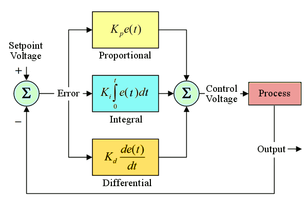
Some background of PID loops may help understand why PID control loops are important to energy efficiency.  At a high level, feedback controllers attempt to minimize the error between a setpoint, say discharge air temperature setpoint, and a measured process variable, such as actual discharge air temperature.  The controller will compare the actual temperature versus the desired temperature and adjust some process control input, such as the chilled water control valve, to minimize the error.  PID controllers allow systems more closely track their setpoints and achieve the efficiencies an engineer has specified.  If an engineer sets the discharge air temperature at 60° F in the middle of winter, a properly tuned PID loop controller will achieve this setpoint instead of operating at the 55° F summer setpoint (thus saving energy back at the chiller plant and at the reheat box).

A proportional-integral-derivative controller (PID controller) uses three separate constant parameters in the algorithm that can be interpreted with respect to time: P (proportional) depends on the present error, I (integral) depend on the accumulation of past errors, and D (derivative) is a prediction of future errors, based on current rate of change.  In the simplest form, the output of a PID loop is described as:

PIDOutput = Pgain × (Error+  1/Itime  × ∫ 〖Error ×dt〗+Dtime ×  dError/dt)

where:
Error = PID Input – PID Setpoint (for direct acting control scenarios)
Pgain = Proportional Gain Term
Itime = Integral Time
Dtime = Derivative Time

Supply Duct Pressure Control
The goal of the linearization process is to create PID input and setpoint equations that describe the controlled process and compensate for all known varying inputs.  For supply duct pressure control, the final linearized equation must apply for any given supply airflow rate, supply duct pressure loss coefficient and supply fan speed (equations are shown in the paper).  Thus, we can establish the following equations for PIDsetpoing and PIDinput:

 PIDsetpoint = FanSpeed_sp = FanSpeed × √((∆P_sp)/∆P)
PIDinput = FanSpeed

Economizer Damper Control
Similar to the supply duct pressure control linearization method described above, the goal of the economizer damper linearization process is to calculate a PID input equation and PID setpoint equation so that each compensates for the known nonlinearities.  For economizer damper control, the following equations can be used:

PIDsetpoint =  %OA_sp ≈ 100% × ((RAT - DAT_sp) / (RAT - OAT))
PIDinput =  %OA  ≈ 100% × ((RAT - DAT) / (RAT - OAT))

Steam Heat Exchanger Leaving Water Temperature
Linearization of the steam heat exchanger system requires measurement of either water flow rate or entering water temperature.  Because obtaining the water temperature is less expensive and more reliable, the following linearization method addresses the case where the entering water temperature is known.  The fundamental equations for water flow are detailed in the paper; this post showcases resulting PID equations:

PIDsetpoint =  %Q_sp = %Q × ((LWT_sp - EWT) / (LWT - EWT))
PIDinput = %Q ≈ SteamValvePosition

All of these equations can be used to the benefit of energy savings by allowing the engineer to specify energy saving setpoints.

As usual, we end with a typical energy conservation measure that is all too often over looked, having parking garage exhaust fans tied into a CO monitor.  This system runs the fan only when the CO levels reach certain levels and greatly reduces the run time of exhaust fans.

ECM:  Parking Garage CO Ventilation
Average kWh Saved per Sq. Ft.:  2.25

Article Author:  Eric Utterson
eutterson@8760engineering.com
Blog Post Author:  Ryan Corrigan

Wednesday, January 23, 2013

Marketing and Rebranding: Selling Green to a Gray Generation

View Paper

At the 35th Association of Energy Engineers annual World Energy Engineering Congress in Chicago, I presented a paper that discussed some of the difficulties the sustainability movement is facing and some of the opportunities for this movement.  The fundamental theme of the paper is that the “green” industry can now be thought of as more a brand and less of a movement.  Realizing the power or marketing and branding, the green industry needs to take control of its image and understand the current marketplace in order to advance the cause of sustainability.  The paper presented three ways the “green” industry can control its image and advance sustainability; the first is through an accurate assessment of the current marketplace, the second is a better understanding of who our customers are and how they consume energy, and the third is the continuous improvement of past goals and restructuring of future goals.


This post will not go into too much detail of each item presented in the paper but I do want to touch on each of these subjects.  The first being an accurate assessment of the current building landscape and the affect this landscape has on the image / brand of “green” building.  As our economy slowly climbs out of the recession we are going to face an overcapacity of building occupancy and an even greater attention to price (sometimes known as the bottom line effect which manifests itself in the most ironic activity called “value engineering”).  The question then is pretty simple, does the “green” industry position itself as a high cost option that helps the environment, or rather as a solution to lower future operating cost?

The second topic centered on who are the people in charge of energy consumption and how does anything “green” create value for them?  The first part of that equation, who are the people in charge of energy consumption, is not as intuitive as one might think.  They are usually a little older and more advanced in their career and the people with the most influence over energy consumption probably reside in the facilities or maintenance department as opposed to the executive suites.  Their main concern is keeping buildings running and satisfying the building occupants, not reducing their energy burden.  This leads to the second part of the equation, how does anything “green” help them?  The answer to this question will force us to address the main drivers of energy consumption in any building, the large motors that operate chillers, compressors, fans, and pumps.  Why install solar panels when the chilled water plant is not automated, what benefit are lighting occupancy sensors if the air handling units are not scheduled to turn off?  We can create tremendous value for facility managers while simultaneously reducing their energy burden by addressing the major sources of energy consumption within a building.

The final topic dealt with building upon past achievements and recognizing future opportunities.  This is a much more open ending topic and one that this engineer is not best suited to answer.  What should our industry do going forward?  How do we best create value for our customers?  All questions that I addressed in the paper but found much more utility by engaging the fellow attendees in what they thought the future of the “green” industry would be.  Let me know what your thoughts are.

As always this blog post will end with kWh counter, this time it comes from one single ECM (energy conservation measure) that automated the chilled water plant of one of our customers (was part of a larger retrofit).

ECM:  Chilled Water Optimization
Payback:  1.46 years
kWh Saved:  338,937

Author:  Ryan Corrigan

Friday, January 18, 2013

Welcome to the 8760 Engineering Blog!

For starters, 8760 Engineering is an engineering firm that is committed to reducing our customers energy burden and making the business case for sustainability. Our motto...Engineered Efficiency Every Hour... may help explain our name:

   365 Days in one year
x   24 Hours in one day
 8760 Hours in a year

The goal of this blog is to spread ideas and information within the mechanical engineering / architecture / energy engineering / environmental / math and science community.  We appreciate you taking the time to skim through our post and encourage you to participate in the discussion.

Come back every other week to peek into the minds of some the best engineers I have ever met.  And if you don't see anything interesting then reach out to us, we are always looking for new ideas!

If you are interested in our company or want a small sampling of the content posted here you can find us on Twitter at @8760Engineering, or search for us on FaceBook and LinkedIn at 8760 Engineering.

Since our goal here is to save customers money by reducing their energy burden and becoming more sustainability, we will end each blog post with a kWh counter that tallies the kWh's we have saved our customers.  This weeks number comes from a job that was done in coordination with Ameren Illinois' ActOnEnergy Program.

Type:  Hospital
Job:  RetroCommissioning
kWh Saved:  2,140,069

Author: Ryan Corrigan
rcorrigan@8760engineering.com